SparkNavi Blue
Overview#
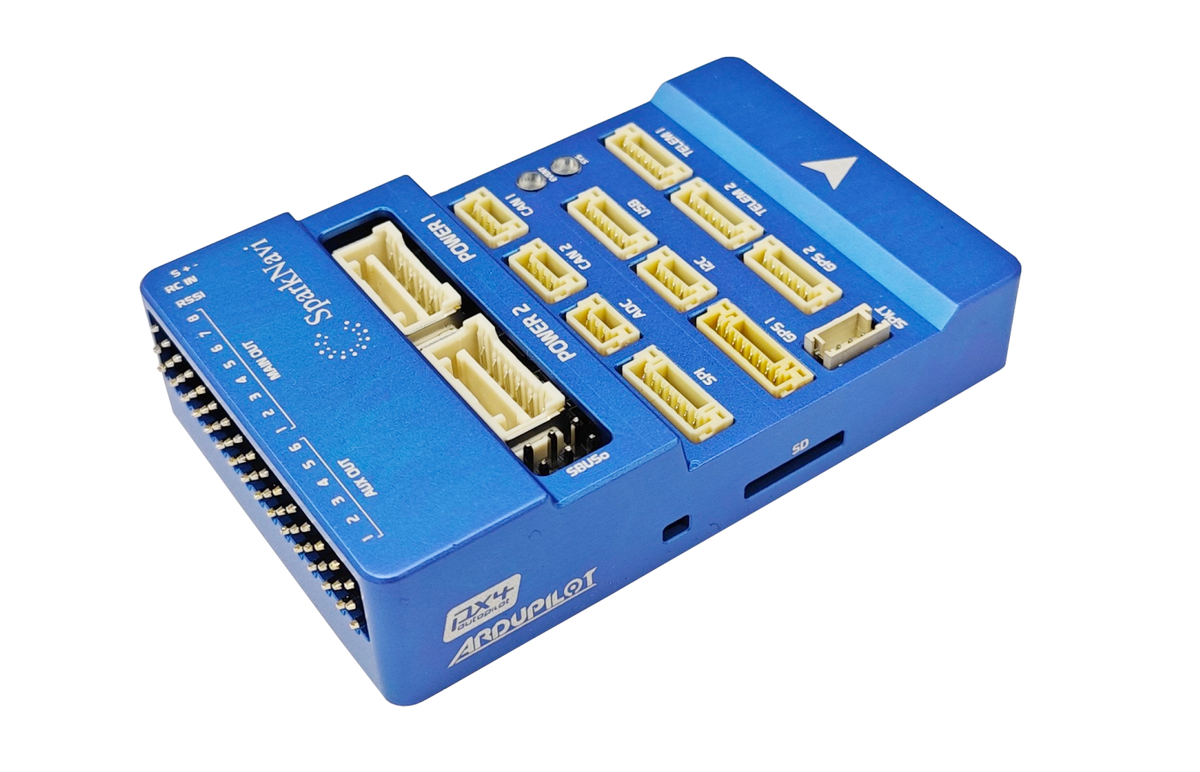
SparkNavi Blue is a high-performance STM32H743 flight control computer designed for professional UAV, robotics, and research platforms.
Fully supported by the ArduPilot ecosystem and engineered for long-lifecycle deployment across industrial and research applications.
Widely deployed across industrial, research, and autonomous platform integrations.
Where to Buy#
SparkNavi Blue is available through our authorized regional distributors. Purchasing through a local distributor gives you faster shipping, local logistics support, and easier after-sales service in your region.
For distributor contact details in the United States & North America, Japan, and Taiwan, please visit our Contact page.
If there is no distributor in your region yet, you can also order directly from us — see the Contact page for sales inquiries.
Flight Demonstration#
Additional flight clips
Key Features#
- CNC machined aluminum enclosure
- STM32H743 MCU (480MHz)
- 2MB Flash
- Dual IMU (ICM42652 + ICM42688)
- External I2C compass support (RM3100 / IST8310)
- CAN FD (2 ports)
- Dual GPS ports
- microSD logging
- Dedicated IOMCU
- Integrated RGB status LED
- USB Type-C
- Compact enclosed design
Manufacturing & Compliance#
Designed and manufactured in Taiwan.
The hardware is built using globally sourced industrial-grade components suitable for customers with strict regulatory, compliance, or export requirements.
Regulatory Compliance
SparkNavi Blue has passed international EMC and safety compliance testing.
FCC (United States)
- 47 CFR FCC Part 15 Subpart B (Class B)
- ANSI C63.4:2014
CE (European Union)
- EN 55032:2015 + A11:2020
- EN 55035:2017 + A11:2020
- EN IEC 61000-3-2:2019 + A2:2024
- EN 61000-3-3:2013 + A2:2021 + AC:2022
PSE (Japan)
- J62368-1:2023
These certifications enable deployment across North America, Europe, and Japan.
Size#
Specifications#
| MCU | STM32H743 (480MHz) |
|---|---|
| IOMCU | STM32F103 |
| Flash | 2MB |
| IMU | ICM42652 + ICM42688 |
| Barometer | BMP280 |
| Internal Compass | HMC5883L |
| CAN | 2× CAN FD |
| UARTs | 6 |
| PWM Outputs | 14 (6 AUX + 8 MAIN via IOMCU) |
| Logging | microSD |
| USB | USB-C |
Main Connectors#
- POWER1 / POWER2
- GPS1 / GPS2
- TELEM1 / TELEM2
- CAN1 / CAN2
- SPI expansion
- ADC expansion
- I2C external bus
- SBUS / RSSI port
UART Mapping#
UART Mapping
| Port | Function | Notes |
|---|---|---|
USART1 | GPS1 | — |
UART4 | GPS2 | — |
USART2 | TELEM1 | — |
USART3 | TELEM2 | — |
UART7 | Debug | — |
UART8 | IOMCU | — |
I2C Buses#
| Bus | Usage |
|---|---|
| I2C2 | External I2C |
| I2C4 | Internal sensors |
External compasses are automatically detected on the external I2C bus.
Connector Overview#
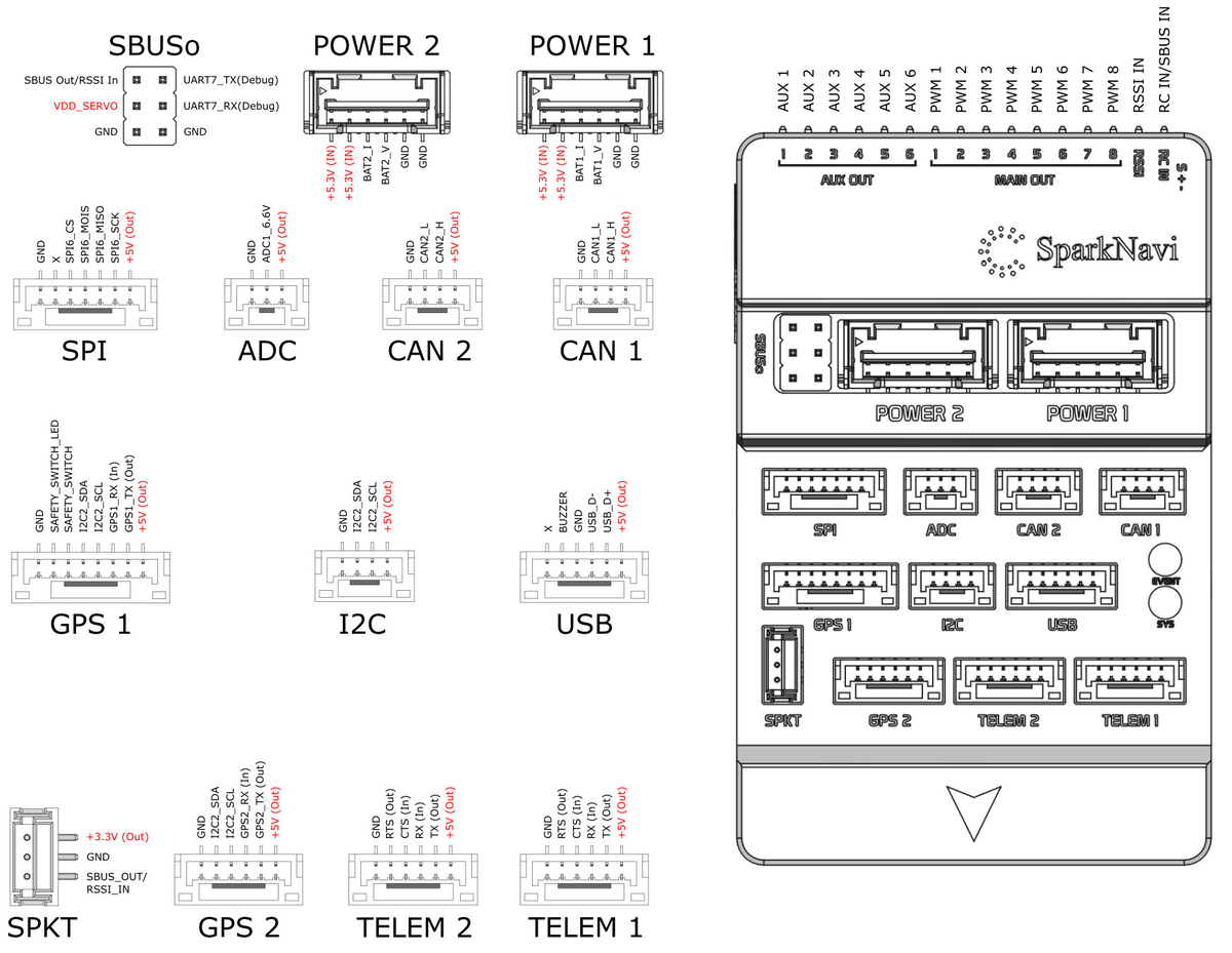
Connector Pin Definitions#
TELEM1 / TELEM2 (Telemetry UART)
| Pin | Signal | Direction | Description |
|---|---|---|---|
| 1 | +5V |
Out | 5V peripheral power |
| 2 | TX |
Out | UART transmit |
| 3 | RX |
In | UART receive |
| 4 | CTS |
In | Flow control (optional) |
| 5 | RTS |
Out | Flow control (optional) |
| 6 | GND |
— | —; Ground |
GPS1
| Pin | Signal | Direction | Description |
|---|---|---|---|
| 1 | +5V |
Out | 5V peripheral power |
| 2 | GPS1_TX |
Out | UART TX to GPS |
| 3 | GPS1_RX |
In | UART RX from GPS |
| 4 | I2C2_SCL |
Out | Compass I2C clock |
| 5 | I2C2_SDA |
— | Bi-Dir; Compass I2C data |
| 6 | SAFETY_SWITCH |
In | Safety button |
| 7 | SAFETY_SWITCH_LED |
Out | Safety switch / LED |
| 8 | GND |
— | —; Ground |
GPS2
| Pin | Signal | Direction | Description |
|---|---|---|---|
| 1 | +5V |
Out | 5V peripheral power |
| 2 | GPS2_TX |
Out | UART TX to GPS |
| 3 | GPS2_RX |
In | UART RX from GPS |
| 4 | I2C2_SCL |
Out | Secondary I2C clock |
| 5 | I2C2_SDA |
— | Bi-Dir; Secondary I2C data |
| 6 | GND |
— | —; Ground |
CAN1 / CAN2
| Pin | Signal | Direction | Description |
|---|---|---|---|
| 1 | +5V |
Out | 5V peripheral power |
| 2 | CAN_H |
— | Bi-Dir; CAN high |
| 3 | CAN_L |
— | Bi-Dir; CAN low |
| 4 | GND |
— | —; Ground |
USB Port
| Pin | Signal | Direction | Description |
|---|---|---|---|
| 1 | +5V |
Out | 5V peripheral power |
| 2 | USB_D+ |
— | Bi-Dir; USB data positive |
| 3 | USB_D- |
— | Bi-Dir; USB data negative |
| 4 | GND |
— | —; Ground |
| 5 | Buzzer |
Out | External buzzer output |
| 6 | x |
— | —; x |
I2C External Port
| Pin | Signal | Direction | Description |
|---|---|---|---|
| 1 | +5V |
Out | 5V peripheral power |
| 2 | I2C2_SCL |
Out | I2C clock |
| 3 | I2C2_SDA |
— | Bi-Dir; I2C data |
| 4 | GND |
— | —; Ground |
ADC Port
| Pin | Signal | Direction | Description |
|---|---|---|---|
| 1 | +5V |
Out | 5V peripheral power |
| 2 | ADC |
In | Analog input |
| 3 | GND |
— | —; Ground |
SPI Expansion Port
| Pin | Signal | Direction | Description |
|---|---|---|---|
| 1 | +5V |
Out | 5V peripheral power |
| 2 | SPI6_SCK |
Out | SPI clock |
| 3 | SPI6_MISO |
In | SPI MISO |
| 4 | SPI6_MOSI |
Out | SPI MOSI |
| 5 | SPI6_CS |
Out | Chip select |
| 6 | x |
— | —; x |
| 7 | GND |
— | —; Ground |
SBUS / RSSI Port (SPKT)
| Pin | Signal | Direction | Description |
|---|---|---|---|
| 1 | +3.3V |
— | — |
| 2 | GND |
— | — |
| 3 | SBUS_OUT / RSSI_IN |
— | — |
POWER1 / POWER2
| Pin | Signal | Direction | Description |
|---|---|---|---|
| 1 | +5.3V (IN) |
— | — |
| 2 | +5.3V (IN) |
— | — |
| 3 | BAT1_I |
— | — |
| 4 | BAT1_V |
— | — |
| 5 | GND |
— | — |
| 6 | GND |
— | — |
Output Architecture#
SparkNavi Blue uses a dual-processor architecture:
- MAIN outputs are driven by the IOMCU (failsafe capable)
- AUX outputs are driven directly by the FMU (high-speed / flexible)
This architecture provides redundancy and improved flight safety.
MAIN Outputs (IOMCU Controlled)#
Primary motor outputs with hardware failsafe support.
| Output | Function | Notes |
|---|---|---|
| MAIN OUT 1 | Motor / Servo | IOMCU controlled |
| MAIN OUT 2 | Motor / Servo | IOMCU controlled |
| MAIN OUT 3 | Motor / Servo | IOMCU controlled |
| MAIN OUT 4 | Motor / Servo | IOMCU controlled |
| MAIN OUT 5 | Motor / Servo | IOMCU controlled |
| MAIN OUT 6 | Motor / Servo | IOMCU controlled |
| MAIN OUT 7 | Motor / Servo | IOMCU controlled |
| MAIN OUT 8 | Motor / Servo | IOMCU controlled |
✔ Hardware failsafe supported
✔ Recommended for motors / critical actuators
AUX Outputs (FMU Controlled)#
Flexible outputs for payloads and advanced peripherals.
| Output | Typical Use |
|---|---|
| AUX OUT 1 | Gimbal / Payload |
| AUX OUT 2 | Gimbal / Payload |
| AUX OUT 3 | Landing gear |
| AUX OUT 4 | Camera trigger |
| AUX OUT 5 | Lights / Buzzer |
| AUX OUT 6 | Custom peripherals |
✔ High update rate supported
✔ Fully configurable in ArduPilot
PWM Summary#
MAIN outputs are driven by the IOMCU.
AUX outputs are driven by the FMU.
| Outputs | Pins |
|---|---|
MAIN OUT | 1–8 |
AUX OUT | 1–6 |
Total | 14 PWM Outputs |
RC Input#
The SBUS connector supports:
- SBUS input
- SBUS output
- RSSI input
Powering the Board#
The controller can be powered from either POWER1 or POWER2.
Both provide:
- Power input
- Voltage/current sensing
- Redundant supply capability
Compass#
External compasses are recommended for optimal flight performance.
Supported models:
- RM3100
- IST8310
Automatic compass rotation detection is enabled.
Firmware Support#
Fully supported in the official ArduPilot firmware distribution.
Board Name: SparkNavi Blue
APJ Board ID: 1362
Supported Firmware
- ArduPilot (Official Support)
Typical Wiring#
Typical wiring includes:
- GPS on GPS1
- Telemetry radio on TELEM1
- External compass on I2C
- ESCs on MAIN outputs
Typical Applications#
- Industrial UAV platforms
- VTOL and multirotor systems
- Autonomous robotics
- Research and development platforms
Electrical Specifications#
| Parameter | Value |
|---|---|
| Operating Voltage | 4.8V – 6.0V |
| Recommended Power Module | 5.3V regulated supply |
| Typical Power Consumption | 0.98W |
| Logic Level | 3.3V |
| GPS Power Output | 5V |
| Peripheral Power Output | 5V |
Power is supplied via POWER1 or POWER2 modules with redundant capability.
Power consumption may vary depending on connected peripherals.
Environmental#
| Operating Temperature | -20°C to +70°C |
|---|---|
| Storage Temperature | -40°C to +85°C |
Mechanical Specifications#
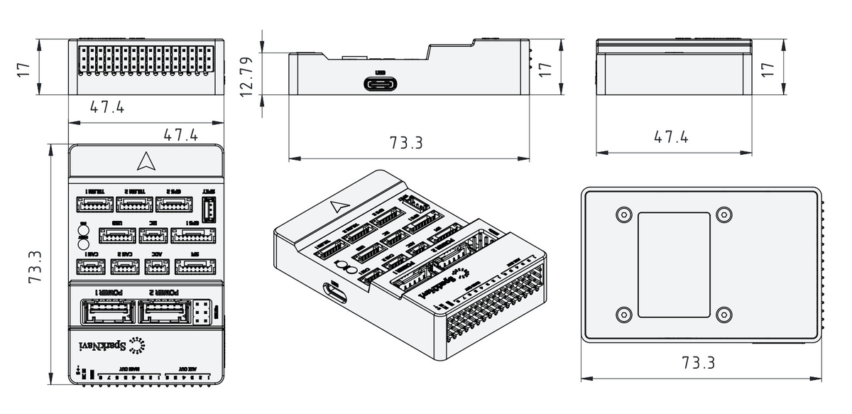
| Length | 73.3 mm |
|---|---|
| Width | 47.4 mm |
| Height | 17 mm |
| Weight | 70 g |
Manufacturer#
SparkNavi
Designed & Manufactured in Taiwan