Airspeed Sensor Setup
An airspeed sensor is essential for fixed-wing (Plane / VTOL) flight. SparkNavi Blue supports both analog and digital (I2C) airspeed sensors.
Analog Airspeed Setup#
Wiring
Connect the analog airspeed sensor to the SparkNavi Blue ADC connector:
| Pin | Signal | Sensor |
|---|---|---|
| 1 | +5V | VCC |
| 2 | ADC | OUT (analog signal) |
| 3 | GND | GND |
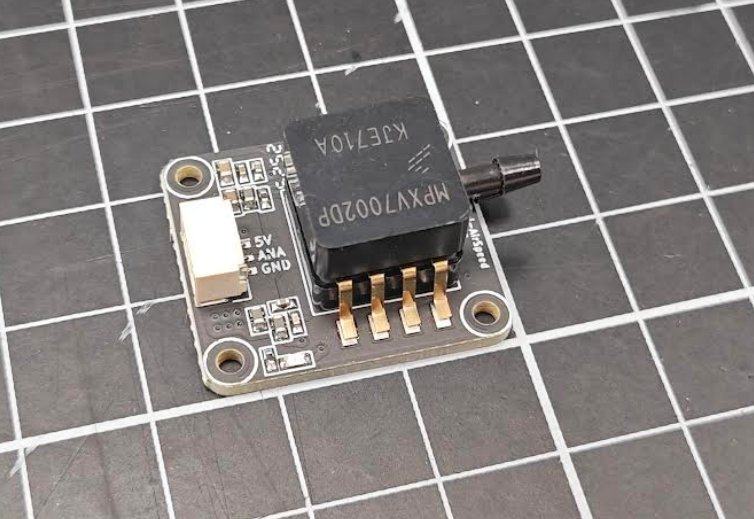
The connector label "ANA" is the analog signal output, which goes to the flight controller's ADC input.
ArduPilot Parameters
| Parameter | Value | Description |
|---|---|---|
ARSPD_TYPE | 2 (Analog) | Analog type |
ARSPD_PIN | 18 | SparkNavi Blue specific |
ARSPD_USE | 1 | Use airspeed for control |
⚠️ Origin of ARSPD_PIN = 18: it corresponds to PA4 (ADC1_6V6_IN), which is ADC1 PIN 18 on the STM32H743 — defined in SparkNavi Blue's hwdef. The Mission Planner dropdown may not list 18; just type it manually.
Calibration
- Configure the parameters above
- Reboot the flight controller
- Blow gently into the Pitot tube's Dynamic port — the AS (Airspeed) value on the Mission Planner HUD should change, confirming setup
Digital Airspeed Setup (MS5525)#
Wiring
Connect MS5525 digital airspeed sensor to SparkNavi Blue's I2C external port:
| Pin | Signal |
|---|---|
| 1 | +5V |
| 2 | I2C2_SCL |
| 3 | I2C2_SDA |
| 4 | GND |
Pitot Tubing
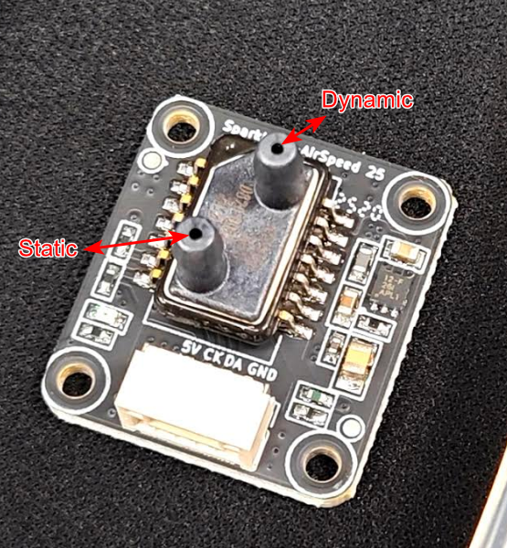
Static (static pressure) connects to the side hole of the Pitot tube; Dynamic (dynamic pressure) connects to the front:
ArduPilot Parameters
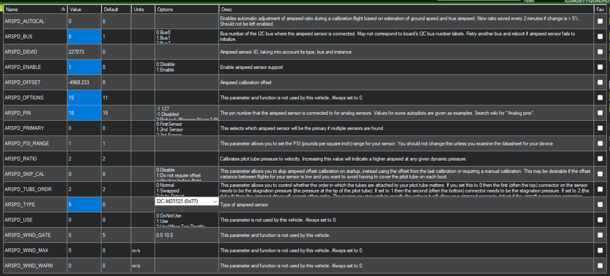
ARSPD_BUS     = 0
ARSPD_OPTIONS = 15
ARSPD_PIN     = 18
ARSPD_TYPE    = 5  (I2C-MS5525, 0x77)
Full parameter table:
Why ARSPD_BUS = 0?
In the SparkNavi Blue hwdef, I2C2 is mapped to bus 0 (highest priority for external I2C peripherals). So ARSPD_BUS = 0 corresponds to the physical I2C2 external port — not the bus literally numbered 0.
I2C Address Conflict
- SPL06 barometer uses I2C address 0x76
- MS5525 default address is also 0x76 → conflicts with SPL06
- Change MS5525 to 0x77 to avoid conflict
- On boards without SPL06, MS5525 at 0x76 is fine
Digital Airspeed Calibration#
After setting parameters:
1. Clear Existing Calibration
ARSPD_SKIP_CAL = 0    ← temporarily disable skip-cal
ARSPD_OFFSET   = 0    ← clear existing offset
Click Write Params.
2. Calibrate
- Cover the Pitot tube opening (no airflow)
- Reboot the SparkNavi Blue
- Check the Mission Planner HUD — AS should read 0 m/s
3. Verify
Check parameters: if ARSPD_OFFSET now has a non-zero value automatically, calibration succeeded.
4. Lock Calibration
ARSPD_SKIP_CAL = 1 ← reuse this calibration on subsequent bootsHUD Verification#
After calibration, the Mission Planner HUD top-left should show AS (Airspeed):
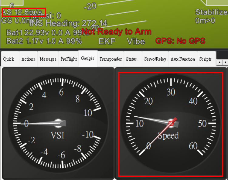
Blow into the Pitot Dynamic port — AS should respond live (e.g., 12.5 m/s).
FAQ#
Q: AS stays at 0 after setup?
A: Check: 1. ARSPD_USE = 1 is enabled 2. I2C wiring correct 3. Pitot Static / Dynamic tubes not swapped 4. Digital sensor I2C address doesn't conflict with another module (use 0x77)
Q: Why does ARSPD_OFFSET stay 0 after reboot?
A: Calibration order matters: block airflow first, then reboot. Wrong order won't calibrate.
Q: AS and GS (groundspeed) differ a lot?
A: That's wind. AS measures speed relative to air; GS measures relative to ground. Headwind makes AS > GS, tailwind makes AS < GS. This is expected.