SparkNavi F9P GPS Module Setup
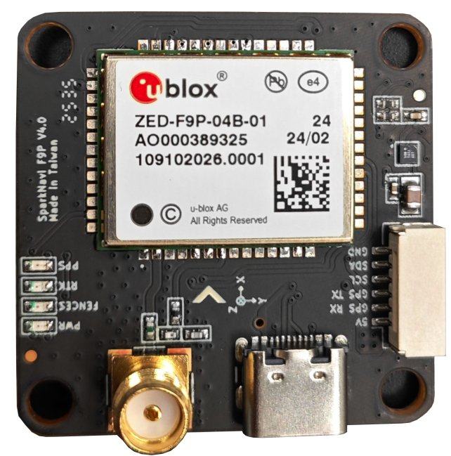
The SparkNavi F9P GPS module combines a u-blox ZED-F9P-04B multi-band RTK receiver with a BMM150 compass on a compact 36.5 × 36.5 mm board. It supports use as GPS1 , GPS2 , or both simultaneously on the SparkNavi Blue flight controller, and is compatible with Pixhawk / ArduPilot / iNAV firmware.
Overview#
Hardware Specifications#
| Category | Value |
|---|---|
GNSS receiver | u-blox ZED-F9P-04B (multi-band L1 / L2 / E5b) |
Constellations | GPS (L1C/A L2C), GLONASS (L1OF L2OF), Galileo (E1-B/C E5b), BeiDou (B1I B2I), QZSS (L1C/A L2C) |
SBAS | WAAS, EGNOS, MSAS, GAGAN, SouthPAN |
Accuracy (antenna-dependent) | <1 cm with base station up to 35 km · 1 cm with NTRIP up to 35 km · 4 cm with SSR · 1.5 m standalone · 0.9 m SBAS |
Update rate | 1 Hz default · up to 10 Hz max performance · up to 20 Hz reduced |
Time to first fix | 25 s cold / 2 s hot · RTK fix 35 s cold |
Compass | Bosch BMM150 (I²C, 3-axis magnetometer) |
Functionality | Base & Rover, RAW UBX output |
Interfaces | UART × 1, USB Type-C × 1 |
Operating temperature | −40 °C to +85 °C |
Dimensions | 36.5 × 36.5 mm, screw spacing 30.5 × 30.5 mm, 10.0 g |
Origin | Designed and manufactured in Taiwan |
Hardware Wiring#
The SparkNavi F9P module uses a 6-pin connector:
| Pin | Signal | Description |
|---|---|---|
| 1 | +5V | Module power |
| 2 | GPS RX | UART receive (from FC TX) |
| 3 | GPS TX | UART transmit (to FC RX) |
| 4 | SCL | I²C clock (BMM150 compass) |
| 5 | SDA | I²C data (BMM150 compass) |
| 6 | GND | Ground |
Connecting to SparkNavi Blue GPS1
GPS1 on SparkNavi Blue is an 8-pin connector. The first 5 signal pins map 1-to-1 with the F9P module; pins 6–7 (SAFETY_SWITCH / LED) on Blue are not used by this module.
| Blue GPS1 Pin | Signal | SparkNavi F9P Pin |
|---|---|---|
| 1 | +5V | 1 (+5V) |
| 2 | GPS1_TX | 2 (GPS RX) |
| 3 | GPS1_RX | 3 (GPS TX) |
| 4 | I2C2_SCL | 4 (SCL) |
| 5 | I2C2_SDA | 5 (SDA) |
| 6 | SAFETY_SWITCH | — (not connected) |
| 7 | SAFETY_SWITCH_LED | — (not connected) |
| 8 | GND | 6 (GND) |
Connecting to SparkNavi Blue GPS2
GPS2 on SparkNavi Blue is a 6-pin connector — a direct 1-to-1 match with the F9P module.
| Blue GPS2 Pin | Signal | SparkNavi F9P Pin |
|---|---|---|
| 1 | +5V | 1 (+5V) |
| 2 | GPS2_TX | 2 (GPS RX) |
| 3 | GPS2_RX | 3 (GPS TX) |
| 4 | I2C2_SCL | 4 (SCL) |
| 5 | I2C2_SDA | 5 (SDA) |
| 6 | GND | 6 (GND) |
ArduPilot Parameters — Single GPS (Primary)#
For a single SparkNavi F9P module connected as GPS1, the default ArduPilot serial settings (GPS UART at 230 400 baud) already work. The key parameters to verify:
| Parameter | Value | Description |
|---|---|---|
GPS1_TYPE | 2 (u-Blox) | u-blox driver (auto-detects F9P) |
GPS_AUTO_CONFIG | 3 | Clear non-ArduPilot config and apply defaults on boot (recommended for u-blox Gen 9+) |
GPS_AUTO_SWITCH | 1 (Use best) | Default — switches based on fix quality |
GPS_PRIMARY | 0 (GPS1) | First instance is primary |
After Write Params and Reboot, Mission Planner Status should show:
- gpsstatus ≥
3(3D fix);4= DGPS,5= RTK Float,6= RTK Fixed - satcount typically 20–30+ with clear sky view (multi-constellation)
ArduPilot Parameters — Dual GPS#
When using two SparkNavi F9P modules (GPS1 + GPS2), both are identical multi-band F9P units. The recommended switching strategy is Blend.
| Parameter | Value | Description |
|---|---|---|
GPS1_TYPE | 2 (u-Blox) | Primary instance |
GPS2_TYPE | 2 (u-Blox) | Secondary instance |
GPS_AUTO_CONFIG | 3 | Clean u-blox config on boot |
GPS_AUTO_SWITCH | 2 (Blend) | Average the two solutions |
GPS_PRIMARY | 0 (GPS1) | First instance is primary when not blending |
GPS_INJECT_TO | 127 (Broadcast) | Forward RTCM correction stream to both GPSes — required for RTK with NTRIP |
GPS Auto Configuration (GPS_AUTO_CONFIG)#
GPS_AUTO_CONFIG controls whether ArduPilot rewrites the GPS module's internal configuration on boot:
| Value | Behavior | When to use |
|---|---|---|
| Disable automatic configuration | Only when using a custom GPS configuration written by hand via u-center — not recommended for the SparkNavi F9P |
| Auto-configure serial GPS modules | Default. Works for most use cases |
| Auto-configure DroneCAN GPS modules as well | Required when configuring GPS for Yaw / Moving Baseline over DroneCAN |
| Clear all non-ArduPilot u-blox config and reapply defaults | Recommended for SparkNavi F9P — guarantees a clean known-good config every boot (u-blox Generation 9+) |
GPS Auto Switch (GPS_AUTO_SWITCH)#
When two GPS units are connected, GPS_AUTO_SWITCH decides which solution ArduPilot uses:
| Value | Behavior | Best for |
|---|---|---|
| Always use the GPS at index | When the secondary unit is only a passive backup |
| Pick the unit with the better fix status (RTK > DGPS > 3D); ties broken by satellite count | General default for two reasonable-quality GPSes |
| Average the two solutions | Two identical SparkNavi F9P modules — recommended |
| Stay on the primary as long as it has a 3D fix; fall back to secondary only on loss | Mixed setup (e.g., one F9P primary + one M8N backup) |
EKF3 also supports GPS affinity with lane switching: an EKF lane can be bound to a specific GPS instance, and the whole lane is switched out if that GPS becomes unhealthy. When GPS_PRIMARY is used for a lane and GPS_AUTO_SWITCH is enabled, the lane will follow the auto-switch decision.
GPS Jamming Mediation (EK3_OPTIONS bit 0)#
For operations in contested or RF-noisy environments (a common requirement for defense and industrial UAV platforms), ArduPilot provides EKF3 jamming mediation:
Setting EK3_OPTIONS bit 0 (JammingExpected) changes EKF3 behavior such that, when GPS lock is lost for more than 2 seconds and dead-reckoning navigation is possible, the preflight alignment GPS quality checks (EK3_GPS_CHECK, EK3_CHECK_SCALE) must pass again before GPS is re-used.
This prevents corrupted GPS data from being immediately consumed by the EKF after re-lock — a likely failure mode under deliberate jamming or spoofing.
BMM150 Compass#
The onboard BMM150 is detected automatically by ArduPilot over the I²C2 bus.
After connecting and rebooting, in Mission Planner Setup → Mandatory Hardware → Compass:
- Verify detection — the BMM150 should appear as an external compass (typically priority 1 if no other external compass is connected)
- Disable internal compasses — for best yaw performance, deselect the FC's internal compasses if external compasses are healthy (SparkNavi Blue has no internal compass, so this step is automatic)
- Set orientation — set
COMPASS_ORIENTto match the physical mounting of the GPS module (the arrow on the PCB silkscreen should point toward the front of the aircraft; if rotated, setCOMPASS_ORIENTaccordingly) - Calibrate — perform the on-board or Mag Cal procedure, rotating the airframe through all axes
Verification#
After full setup, the Mission Planner HUD should show:
- 3D Fix or better within 30 seconds outdoors
- Sat count typically 20–30+ with clear sky
- HDOP below 1.0 within 1 minute
- RTK Fixed within ~35 seconds when a base station / NTRIP correction is active
For RTK operation, set GPS_INJECT_TO = 127 and stream RTCM3 corrections from Mission Planner (Initial Setup → Optional Hardware → RTK GPS Inject) or a custom NTRIP client.