RSSI Receiver Setup
RSSI (Received Signal Strength Indicator) monitors the signal strength from the transmitter to the receiver. SparkNavi Blue supports two RSSI input methods:
Overview#
- Via any S.BUS channel (recommended — simplest wiring)
- Direct RSSI Out pin to flight controller's RSSI IN Pin (IOMCU_SBUS_INPUT, IOMCU PB11)
Mission Planner Parameters#
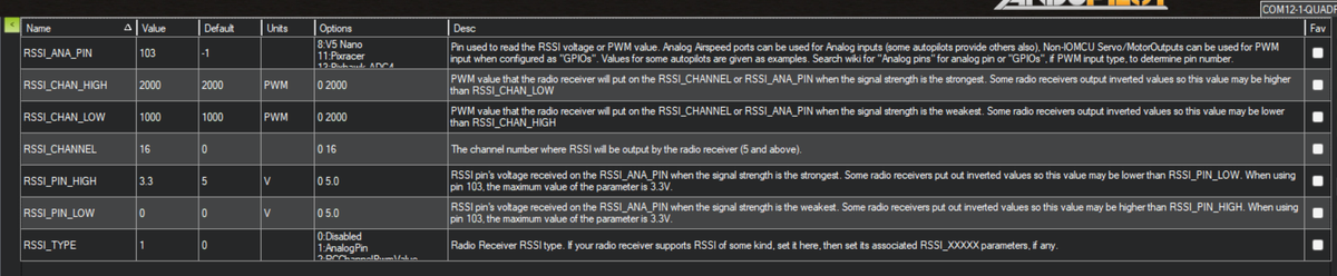
In Mission Planner Config → Full Parameter List:
| Parameter | Value | Description |
|---|---|---|
RSSI_TYPE | 1 | Set to AnalogPin type |
RSSI_ANA_PIN | 103 | Maps to SparkNavi Blue's RSSI analog pin |
RSSI_CHANNEL | 16 | Transmit RSSI via S.BUS channel 16 |
RSSI_PIN_HIGH | 3.3 | Maximum voltage at full signal (SparkNavi Blue uses 3.3 V logic) |
Hardware Wiring#
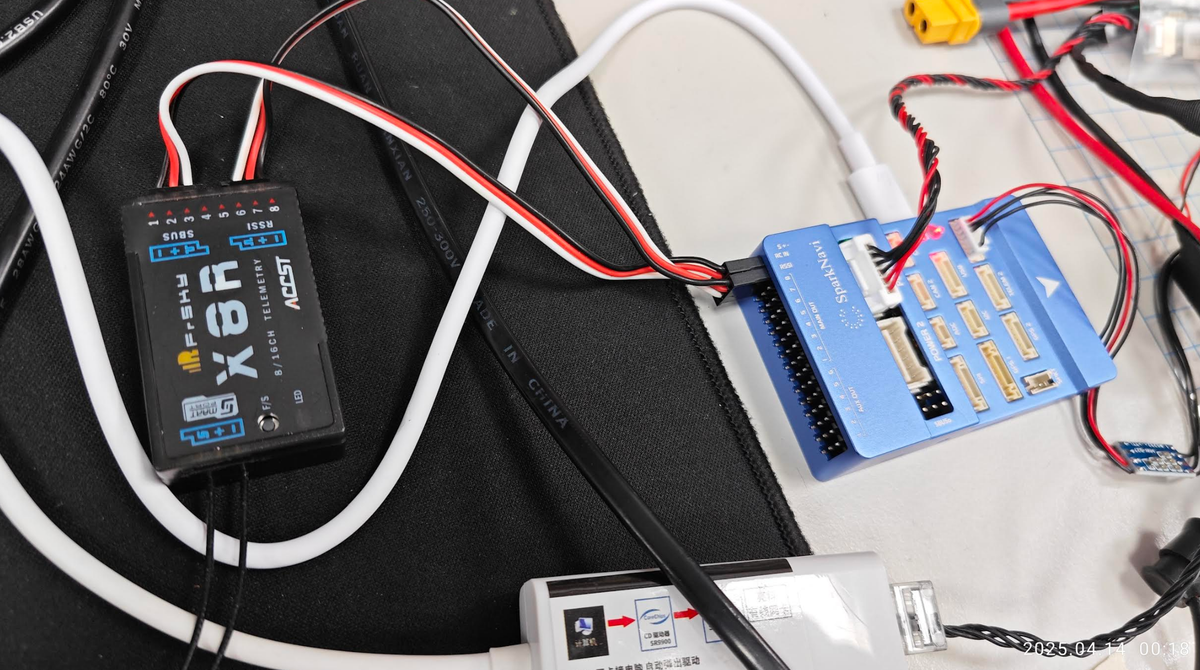
Using a FrSky X8R receiver as example: connect its RSSI pin to the SparkNavi Blue's RSSI Pin.
Transmitter Setup (Taranis Example)#
1. Add RSSI Input
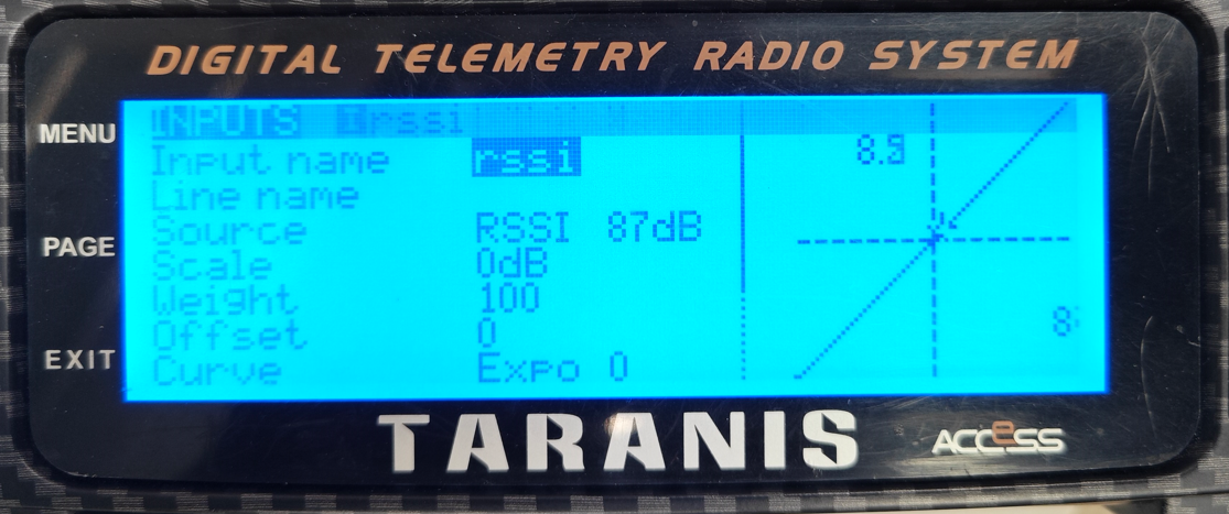
In the INPUTS page, add an rssi channel with Source = RSSI, Scale = 0 dB.
2. Map to CH16 in MIXES
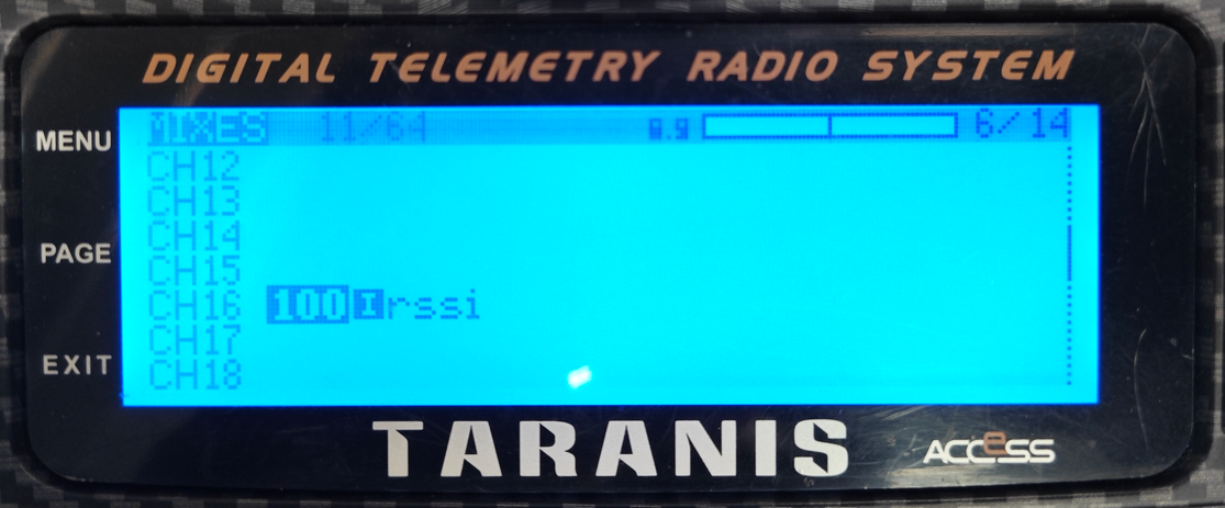
In the MIXES page, map CH16 to the rssi input you just created with Weight = 100.
This corresponds to ArduPilot's RSSI_CHANNEL = 16.
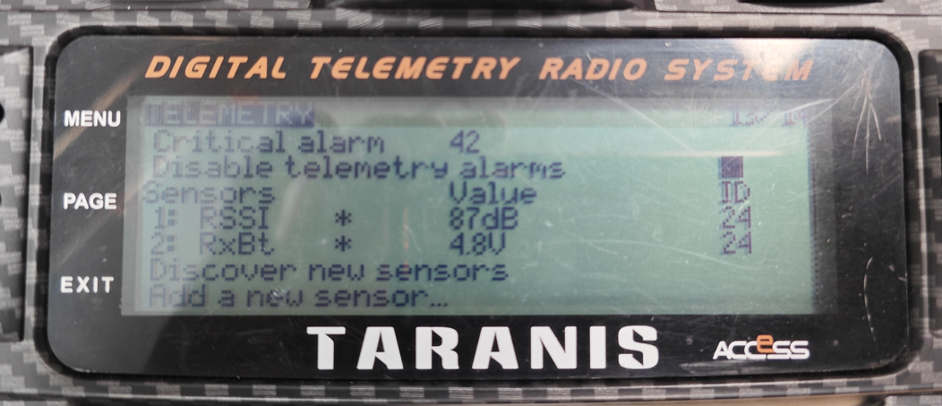
3. Verify in TELEMETRY
On the TELEMETRY page, after Discover new sensors, RSSI should appear. RxBt is the receiver voltage.
Verification#
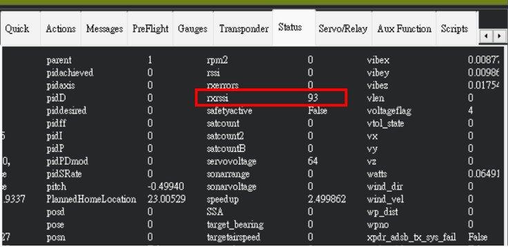
Once configured, the rxrssi value should appear live in Mission Planner's Status page or Quick tab.
Test it by physically removing the receiver antenna — the value should drop immediately. Higher = stronger signal.
FAQ#
Q: rxrssi is not showing after setup?
A: Check: 1. RSSI_TYPE is set to 1 2. RSSI_CHANNEL matches the channel configured in your transmitter MIXES 3. Reboot the flight controller and re-check
Q: Why is RSSI_ANA_PIN = 103 for SparkNavi Blue?
A: 103 is the Pixhawk SBUS analog pin, which on SparkNavi Blue maps to the IOMCU PB11 pin (IOMCU_SBUS_INPUT) — that's how Blue's hwdef defines it. Other Pixhawk-class boards may use different pin numbers.