VD-Link Telemetry / Video Setup
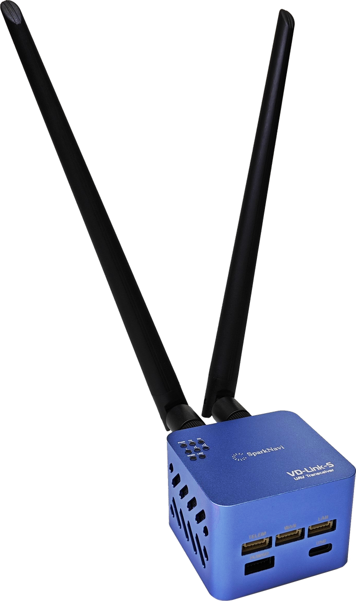
The SparkNavi VD-Link-S is a dual-band (2.4 GHz + 900 MHz) long-range wireless datalink based on Microhard radio modules. With an effective range of 5 km , it can simultaneously transmit:
Overview#
- Telemetry data (MAVLink, from the SparkNavi Blue flight controller)
- Visible-light IP camera video (via WAN port)
- Thermal / IR camera video (via LAN port)
This guide covers the full flow: wiring, Microhard configuration, video streaming, and TX Power tuning.
⚠️ Critical Safety Warning (Read First)#
System Architecture#
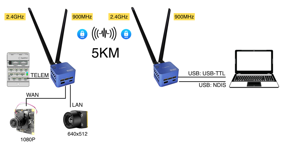
VD-Link uses a Sky-side (aircraft) + Ground-side (GCS) two-module design with AES encryption on all signals:
| Component | Aircraft side | Ground side |
|---|---|---|
| Flight controller | SparkNavi Blue → TELEM | — |
| 1080P IP camera | → WAN | — |
| 640×512 thermal camera | → LAN | — |
| GCS PC | — | USB-TTL (telemetry) / USB-NDIS (video) |
Hardware Port Layout#
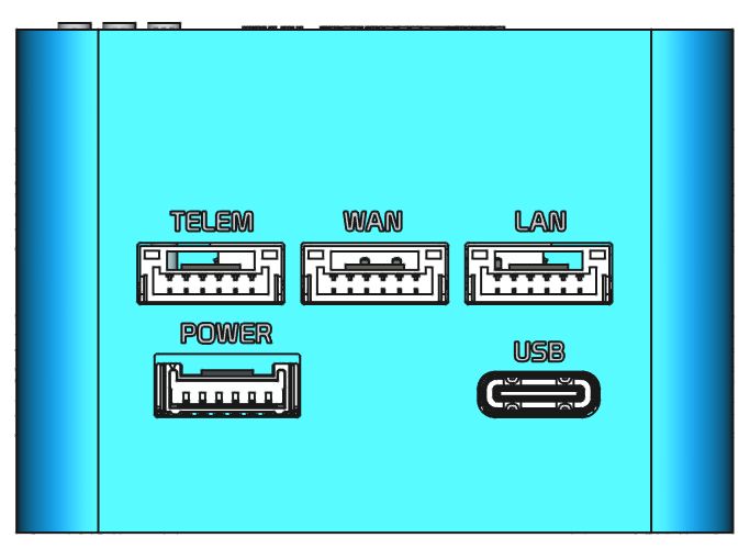
Bottom face of the VD-Link module:
| Port | Purpose | Connector |
|---|---|---|
TELEM | FC telemetry (to SparkNavi Blue) | GH1.25 6-pin |
WAN | IP camera (visible) — RTSP stream | GH1.25 6-pin, +12V output |
LAN | Thermal / secondary video — RTSP stream | GH1.25 6-pin, +12V output |
POWER | Power input (max +55V / 12S) | GH1.25 |
USB | Ground PC USB Type-C (NDIS network + USB-TTL telemetry) | USB-C |
Antenna Assignment
| Antenna port | Band |
|---|---|
ANT1 | 2.4 GHz |
ANT2 | 900 MHz |
The dual-band design avoids single-band interference; if one band fails, the link automatically falls back to the other.
Complete Wiring Diagram#
Typical aircraft-side wiring: SparkNavi Blue + visible IP camera + thermal camera
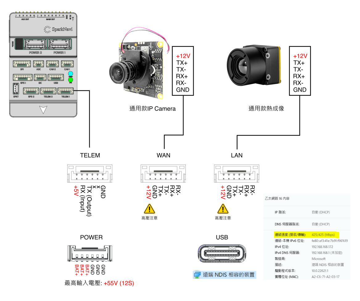
Pin definitions for each GH1.25 connector:
| Pin | TELEM | WAN | LAN | POWER |
|---|---|---|---|---|
| 1 | +5V | +12V | +12V | BAT+ |
| 2 | RX (Input) | TX+ | TX+ | BAT+ |
| 3 | TX (Output) | TX- | TX- | BAT+ |
| 4 | × | RX+ | RX+ | GND |
| 5 | × | RX- | RX- | GND |
| 6 | GND | GND | GND | GND |
⚠️ Reminder: Pin 1 of WAN / LAN is +12V output (camera power). If miswired to FC TELEM, that 12V hits the flight controller's 5V logic circuitry directly.
Web Admin Login#
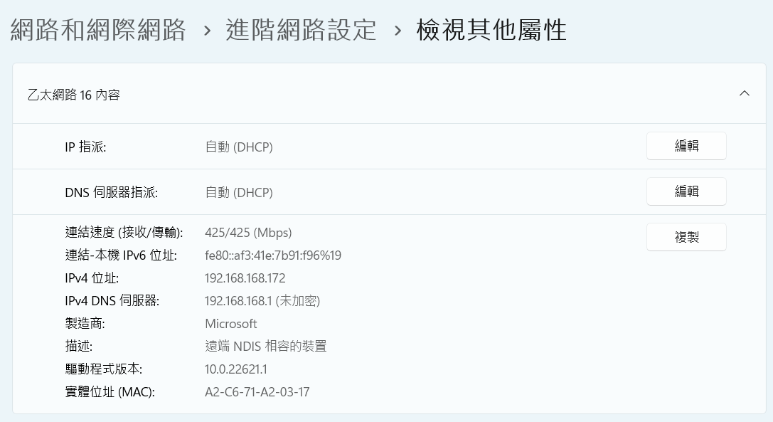
When the ground-side VD-Link is connected via USB Type-C, Windows automatically detects it as a Remote NDIS Compatible Device and obtains an IP automatically (typically in the 192.168.168.x range).
NDIS link speed is up to 425 Mbps, sufficient for dual high-resolution video streams:
Open a browser and access the Microhard web UI:
| Item | Default value |
|---|---|
| URL |
|
| Username |
|
| Password |
|
Microhard Master Configuration (Ground Side)#
In the Microhard web UI → Serial → Settings:
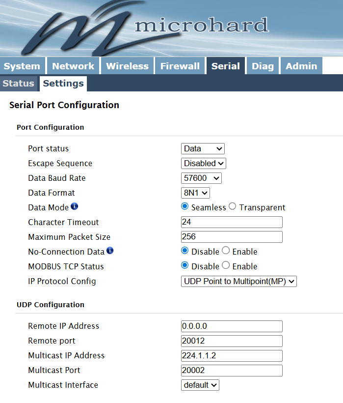
Port Configuration
| Field | Value |
|---|---|
Port status |
|
Escape Sequence |
|
Data Baud Rate |
|
Data Format |
|
Data Mode |
|
Character Timeout |
|
Maximum Packet Size |
|
No-Connection Data |
|
MODBUS TCP Status |
|
IP Protocol Config |
|
UDP Configuration
| Field | Value |
|---|---|
| Remote IP Address |
|
| Remote port |
|
| Multicast IP Address |
|
| Multicast Port |
|
| Multicast Interface |
|
Microhard Slave Configuration (Aircraft Side)#
In the Slave-side Microhard web UI → Serial → Settings:
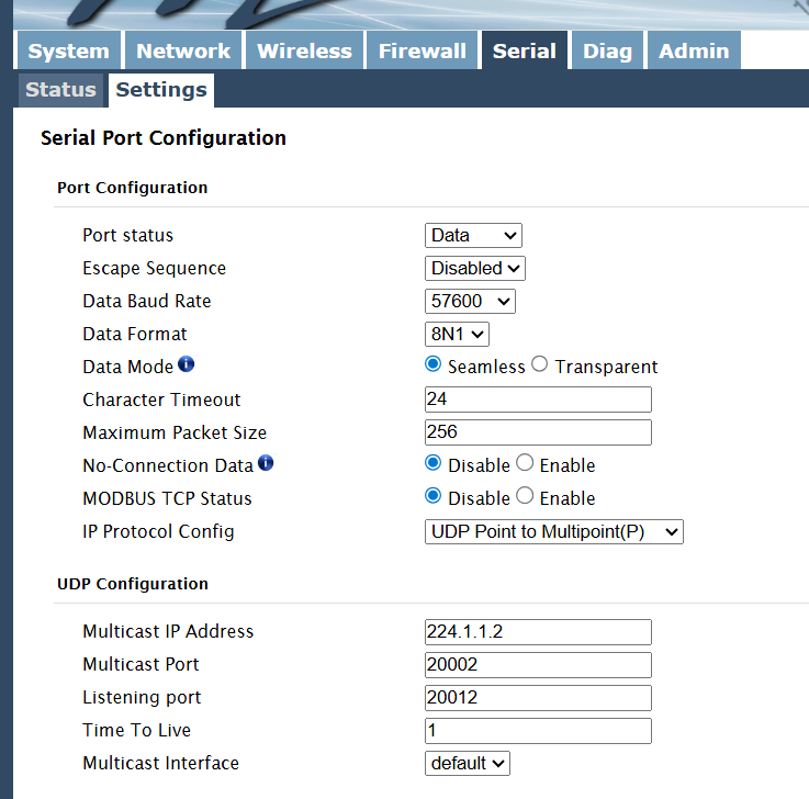
Port Configuration
Same as Master (Data Baud Rate = 57600, IP Protocol = UDP Point to Multipoint).
UDP Configuration
| Field | Value |
|---|---|
Multicast IP Address |
|
Multicast Port |
|
Listening port |
|
Time To Live |
|
Multicast Interface |
|
⚠️ Key difference: the Slave has Listening port = 20012, matching the Master's Remote port = 20012.
TX Power Tuning (Important Operational Tip)#
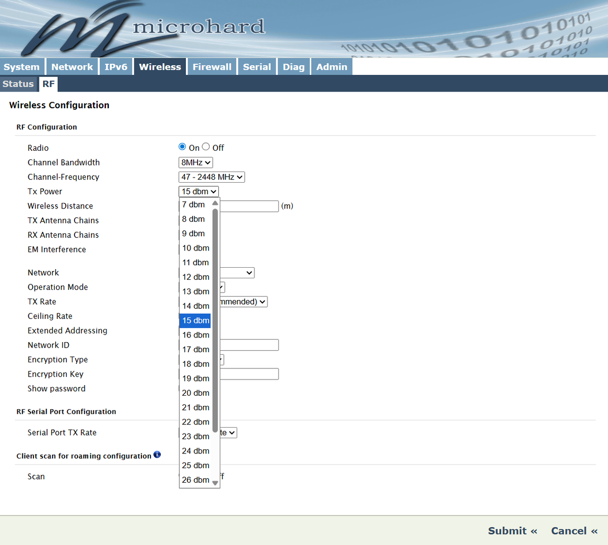
| Scenario | Recommended TX Power |
|---|---|
| Desktop loop test (< 1 meter) | 10 dBm |
| Close-range function test (1–10 meters) | 15 dBm |
| Production / flight test (> 50 meters) | 30 dBm |
Configuration path: Microhard web UI → Wireless → RF → Tx Power:
Ground-Side GCS Connection#
Mission Planner Telemetry Link
Connection settings:
- Connection type: UDP
- Listen Port:
20002(matches the Multicast Port)
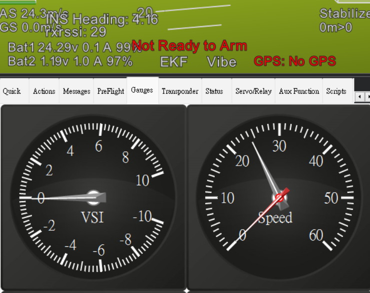
Click Connect — Mission Planner should receive MAVLink heartbeats from SparkNavi Blue.
The HUD should display flight data:
Video Streaming (RTSP)#
The Sky-side IP camera (connected to the WAN port) streams over the NDIS network to the ground PC. Default RTSP URL:
rtsp://admin:admin@192.168.168.88/11(IP varies by your IP camera configuration; the above is a typical example.)
Display Video Using GStreamer (Windows + NVIDIA GPU)
Three command variants for different scenarios. All support automatic reconnection after signal loss:
Option 1: Standard D3D11 (Windows DirectX, best compatibility)
gst-launch-1.0.exe rtspsrc location=rtsp://admin:admin@192.168.168.88/11 protocols=udp latency=0 drop-on-latency=true ! rtph264depay ! h264parse ! nvh264dec ! d3d11videosink sync=false async=false qos=falseOption 2: OpenGL output (slightly lower latency)
gst-launch-1.0.exe rtspsrc location=rtsp://admin:admin@192.168.168.88/11 protocols=udp latency=0 drop-on-latency=true ! rtph264depay ! h264parse ! nvh264dec ! glimagesink sync=false async=false qos=falseOption 3: CUDA direct-to-GL (lowest latency on NVIDIA cards)
gst-launch-1.0.exe rtspsrc location=rtsp://admin:admin@192.168.168.88/11 protocols=udp latency=0 drop-on-latency=true ! rtph264depay ! h264parse ! nvh264dec cuda-device-id=0 ! cudadownload ! glimagesink sync=false async=false qos=falseRequirements
- GStreamer 1.0+: official download
- Choose MSVC + Complete package during install
- Includes
nvh264dec(NVIDIA Video Codec SDK)
If you use an AMD or Intel iGPU, replace nvh264dec with: - AMD: d3d11h264dec - Intel QuickSync: mfh264dec
FAQ#
Q: Mission Planner doesn't receive UDP packets?
A: Check: 1. Master and Slave Multicast IP / Port match 2. Firewall isn't blocking UDP port 20002 3. Slave Microhard is actually receiving serial data (check Serial Status in Microhard web UI) 4. SparkNavi Blue's SERIAL1_PROTOCOL = 2 and SERIAL1_BAUD = 57 are set correctly
Q: On bench, Mission Planner connection is intermittent?
A: That's TX Power saturation. Drop to 10–15 dBm — see the TX Power section above.
Q: NDIS device doesn't appear in Windows?
A: Check: 1. The USB Type-C cable supports data transfer (some USB-C cables are charge-only) 2. Device Manager → Network Adapters shows "Remote NDIS Compatible Device" 3. Try unplugging and waiting 10 seconds before reconnecting
Q: gst-launch shows a black screen?
A: Check: 1. RTSP IP / credentials are correct (camera default is usually admin:admin, NOT the Microhard admin:sparknavi) 2. Camera path /11 is the main stream; /12 is typically a sub-stream 3. Firewall isn't blocking UDP
Q: Why Multipoint instead of Point-to-Point?
A: In Multipoint mode, multiple ground GCS can simultaneously receive data from one aircraft (command center + operator + monitoring PC all connect at once).