STORM32 Gimbal Setup
STORM32BGC is a popular open-source three-axis gimbal controller. This guide covers wiring and ArduPilot parameter setup with the SparkNavi Blue.
Hardware Specs and Power#
- Voltage: STORM32 main board accepts 10 V – 16.8 V input; a 3S Li-Po battery is recommended (4S is also supported up to 16.8 V full).
- Current: 0.5 A (gimbal control board only — motors are separate)
- GUI software: STORM32 BGC Tool v0.90 (older but stable)
⚠️ Use v0.90 GUI for tuning; newer GUI builds have compatibility issues with older STORM32 firmware.
Wiring Map#
| Gimbal Axis | SparkNavi Blue Pin | ArduPilot Parameter | RC Channel |
|---|---|---|---|
| PITCH | AUX1 |
| RCIN9 |
| ROLL | AUX2 |
| RCIN10 |
| YAW | AUX3 |
| RCIN11 |
| Lock / Follow | AUX4 |
| RCIN6 |
Lock mode locks the yaw axis to a fixed direction (e.g., forward); when enabled, the camera stays pointed in that direction regardless of how the aircraft rotates. Most typical applications use Lock mode.
STORM32 Board Wiring Reference#
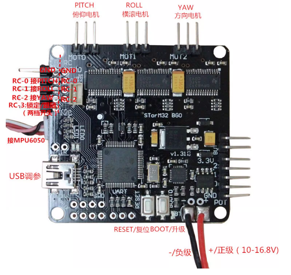
The image below shows the STORM32 BGC board pinout. RC-0 / RC-1 / RC-2 receive PITCH / ROLL / YAW signals. USB is for tuning.
STORM32 GUI Tuning#
Connect the STORM32 BGC to your computer via mini USB and open STORM32 BGC Tool v0.90:
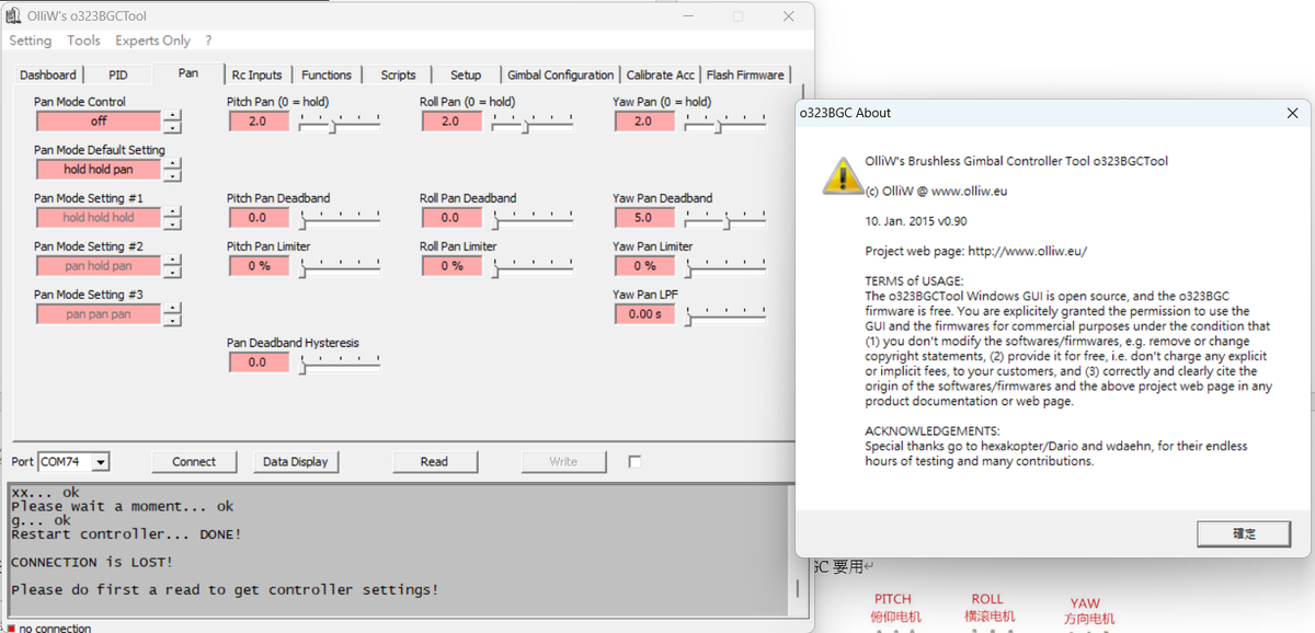
Adjust parameters on the PID (stability) and Pan (auto-follow) tabs. Tuning values vary by gimbal model. Stiffer PID values give better wind / disturbance rejection, but cause the motors to heat up rapidly.
ArduPilot Configuration#
1. Verify RC Channels
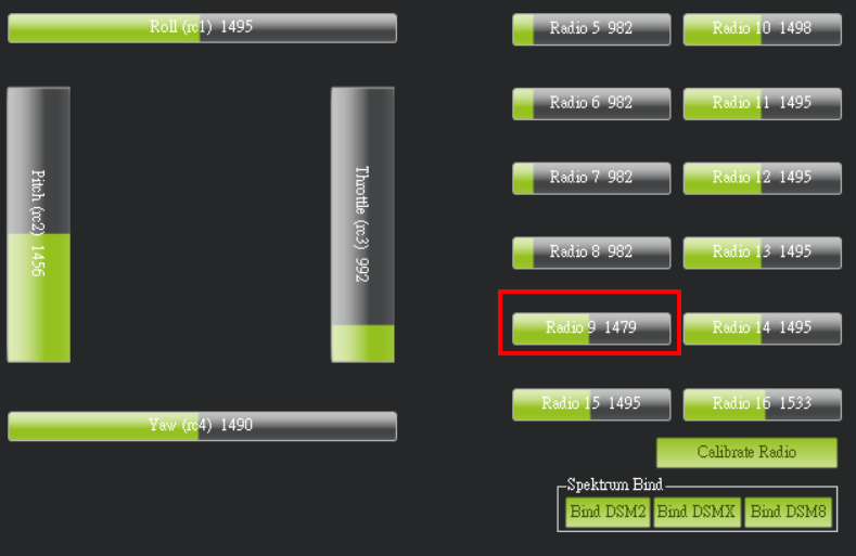
In Mission Planner Setup → Mandatory Hardware → Radio Calibration, confirm Radio 9 / 10 / 11 respond to your transmitter knobs.
2. Set SERVO Functions
In Config → Full Parameter List:
| Parameter | Value | Description |
|---|---|---|
SERVO9_FUNCTION | 59 (RCIN9) | PITCH passthrough from RC 9 |
SERVO10_FUNCTION | 60 (RCIN10) | ROLL passthrough from RC 10 |
SERVO11_FUNCTION | 61 (RCIN11) | YAW passthrough from RC 11 |
SERVO12_FUNCTION | 56 (RCIN6) | Lock / Follow toggle from RC 6 |
You may also adjust PWM ranges:
| Parameter | Value | Description |
|---|---|---|
SERVO9_MIN | 1100 | Minimum PWM |
SERVO9_MAX | 1900 | Maximum PWM |
SERVO9_TRIM | 1500 | PWM mid |
SERVO9_REVERSED | 0 or 1 | Reverse direction |
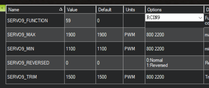
Same approach for SERVO10–SERVO12.
Using Lock Mode#
After setup, flip the RC6 switch on your transmitter (typically a 2-position switch):
- OFF: Follow mode — gimbal follows the aircraft attitude
- ON: Lock mode — gimbal YAW locked to the current heading; the camera stays fixed when the aircraft rotates